Basic Circuit
Simple_low_pass_filter
Published:2009/7/24 13:49:00 Author:Jessie | From:SeekIC

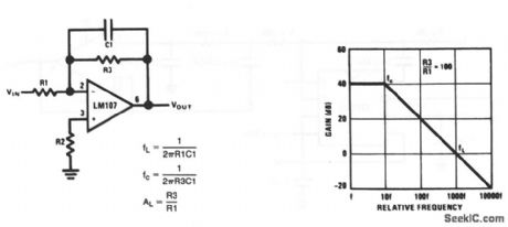
This circuit has a 6-dB per octave rolloff, after a closed-loop 3-dB point that is defined by fc(Fig. 7-41B). Gain below the fc corner frequency is defined by the ratio of R3 to R1. The circuit can be considered as an integrator at frequencies well above fc. However, the time-domain response is that of a single RC, rather than an integral. R2 should be chosen equal to the parallel combination of R1 and R3 to minimize bias-current errors. The op amp should be compensated for unity-gain, or an internally compensated op amp should be used. National Semiconductor, Linear Applications Handbook, 1991, p. 23, 24.
Reprinted Url Of This Article:
http://www.seekic.com/circuit_diagram/Basic_Circuit/Simple_low_pass_filter.html
Print this Page | Comments | Reading(3)

Article Categories
power supply circuit
Amplifier Circuit
Basic Circuit
LED and Light Circuit
Sensor Circuit
Signal Processing
Electrical Equipment Circuit
Control Circuit
Remote Control Circuit
A/D-D/A Converter Circuit
Audio Circuit
Measuring and Test Circuit
Communication Circuit
Computer-Related Circuit
555 Circuit
Automotive Circuit
Repairing Circuit
Code: