Basic Circuit
SQUIB_FIRING_CIRCUIT_Ⅱ
Published:2009/7/1 20:54:00 Author:May | From:SeekIC

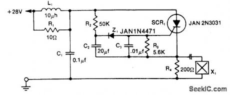
The LRC input network limits the anode dvidt to a safe value-below 30V/μs. R1 provides critical damping to prevent voltage overshoot. While a simple RC filter section could be used, the high current required by the squib would dictate a small value of resistance and a much larger capacitor. Resistor R3 provides dc bias stabilization, while C3 provides stiff gate bias during the transient interval when anode voltage is applied.The SCR is fired one second after arming by means of the simple R2C2Z1 time delay network. R4 provides a load for the SCR for testing the circuit with the squib disconnected-limiting the current to a level well within the continuous rating of the SCR.The circuit can be reset by opening the +28 V supply and then re-arming.
Reprinted Url Of This Article:
http://www.seekic.com/circuit_diagram/Basic_Circuit/SQUIB_FIRING_CIRCUIT_Ⅱ.html
Print this Page | Comments | Reading(3)

Article Categories
power supply circuit
Amplifier Circuit
Basic Circuit
LED and Light Circuit
Sensor Circuit
Signal Processing
Electrical Equipment Circuit
Control Circuit
Remote Control Circuit
A/D-D/A Converter Circuit
Audio Circuit
Measuring and Test Circuit
Communication Circuit
Computer-Related Circuit
555 Circuit
Automotive Circuit
Repairing Circuit
Code: