Basic Circuit
SINGLE_CHIP_FREQUENCY_DOUBLER
Published:2009/7/6 20:21:00 Author:May | From:SeekIC

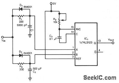
The frequency doubler uses only one IC. Like other doublers, this circuit uses both the rising and falling edges of the input signals to produce digital pulses, thus effectively doubling the input's frequency.Without the rc networks at IC1 inputs, IC1 would not produce any output pulses. However, the rc networks delay one edge with respect to the other. The A input lags the B input for positive-going edges, and the B input lags the A input for negative-going ones. You can vary the output duty cycle from 0 to 100% by varying R3. IC1's minimum output pulse width defines the maximum frequency of this circuit.
Reprinted Url Of This Article:
http://www.seekic.com/circuit_diagram/Basic_Circuit/SINGLE_CHIP_FREQUENCY_DOUBLER.html
Print this Page | Comments | Reading(3)

Article Categories
power supply circuit
Amplifier Circuit
Basic Circuit
LED and Light Circuit
Sensor Circuit
Signal Processing
Electrical Equipment Circuit
Control Circuit
Remote Control Circuit
A/D-D/A Converter Circuit
Audio Circuit
Measuring and Test Circuit
Communication Circuit
Computer-Related Circuit
555 Circuit
Automotive Circuit
Repairing Circuit
Code: