Basic Circuit
SIMPLE_LOW_FREQUENCY_V_F_CONVERTER
Published:2009/7/11 5:28:00 Author:May | From:SeekIC

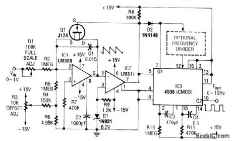
In this circuit, C1 is charged to a fixed reference level, then discharged. Integrator IC1 circuit charges C1 until IC1 has -6.2-V output, when comparator IC2 outputs a low. FET Q1, triggers one-section monostable multivibrator IC3, pulls pin 3 1ow for 470 μs, ensuring that Q1 completely discharges C1. The other section of IC3 produces a longer pulse of about 47 ms.Full scale of this circuit is 10 Hz. For lower output pulse rates, a counter circuit can be inserted between the sections of IC3. Notice that because C1 does not integrate while Q1 is biased on, this circuit has an error in the output period, which must be as short as possible. Therefore, the circuit's use is limited to low frequencies.
Reprinted Url Of This Article:
http://www.seekic.com/circuit_diagram/Basic_Circuit/SIMPLE_LOW_FREQUENCY_V_F_CONVERTER.html
Print this Page | Comments | Reading(3)

Article Categories
power supply circuit
Amplifier Circuit
Basic Circuit
LED and Light Circuit
Sensor Circuit
Signal Processing
Electrical Equipment Circuit
Control Circuit
Remote Control Circuit
A/D-D/A Converter Circuit
Audio Circuit
Measuring and Test Circuit
Communication Circuit
Computer-Related Circuit
555 Circuit
Automotive Circuit
Repairing Circuit
Code: