Basic Circuit
SIGNAL_TRACK_AND_HOLD
Published:2009/7/8 4:34:00 Author:May | From:SeekIC

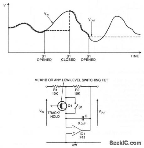
When the switch is closed or the FET is conducting, the circuit behaves as an inverting amplifier with a gain of R2/R1. Since as the inverting terminal of the op amp is a virtual ground, the capacitor is kept charged to the output voltage by the op amp. When the switch is opened and the FET is nonconducting, the voltage at the output is held constant by the capacitor, the current demands of the next stage are met by the op amp. The value of C should be chosen so that its impedance at the operating frequency is large compared to R1 and R2.
Reprinted Url Of This Article:
http://www.seekic.com/circuit_diagram/Basic_Circuit/SIGNAL_TRACK_AND_HOLD.html
Print this Page | Comments | Reading(3)

Article Categories
power supply circuit
Amplifier Circuit
Basic Circuit
LED and Light Circuit
Sensor Circuit
Signal Processing
Electrical Equipment Circuit
Control Circuit
Remote Control Circuit
A/D-D/A Converter Circuit
Audio Circuit
Measuring and Test Circuit
Communication Circuit
Computer-Related Circuit
555 Circuit
Automotive Circuit
Repairing Circuit
Code: