Basic Circuit
SHAFT_ENCODER_PULSE_GENERATING_CIRCUIT
Published:2009/7/13 22:42:00 Author:May | From:SeekIC
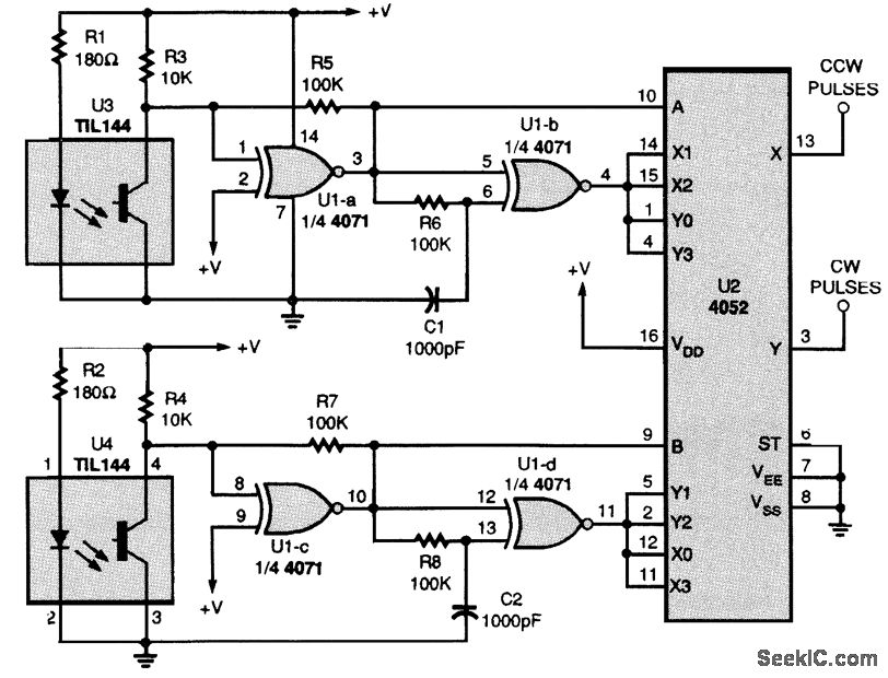
This circuit produces one output pulse for every transition of the photosensor output or four pulses for every section or line pair. The exclusive-NOR gates U1-b and U1-c produce a pulse on every transition, and U2, a dual four-channel data selector, decodes them into up pulses or down pulses. The number of sections or lines that can be accommodated on a disk is determined by its diameter and the width of the sections. As an example, if the sections are made approximately 0.125 wide, 25 section pairs can put on a 2 diameter disk and 100 pulses will be generated with every revolution of the disk. The only limiting factor is that the sections must be wider than the photosensor's aperture at the point they pass in front of it, The alignment of the photosensor assembly is not critical. The only concern is that one sensor be over a light area while the other sensor is at a transition from light to dark or dark to light. 1Vro sections of U1, U1-a and U1-c, act as buffers and waveshapers for the outputs of the sensor, while U1-b and U1-d generate a pulse at each transistor of the sensor's output. The 100-k Ω resistors between the output and the input of U1-a and U1-c provide positive feedback to speed up the rise and fall times and also generate hysteresis to eliminate noise during the transitions. The pulses produced by U1-b and U1-d at the transitions are the result of the delay produced by the RC circuits located at one input of each gate. For example, U1-b pin 5 follows the transition immediately, whereas pin 6 follows slowly. With the values shown, the two inputs are different for about 100 μs after every transition. While the inputs are different, the output is low. Therefore, U1-b generates a negative pulse for every transition of sensor U3 and U1-d generates a negative pulse for every transition of U4. The states of U3 and U4 determine whether the pulse is sent to the X output of the data selector (U2, pin 13) to indicate a CCW pulse or to the Y output (pin 3) to indicate a CW pulse.
Reprinted Url Of This Article:
http://www.seekic.com/circuit_diagram/Basic_Circuit/SHAFT_ENCODER_PULSE_GENERATING_CIRCUIT.html
Print this Page | Comments | Reading(3)

Article Categories
power supply circuit
Amplifier Circuit
Basic Circuit
LED and Light Circuit
Sensor Circuit
Signal Processing
Electrical Equipment Circuit
Control Circuit
Remote Control Circuit
A/D-D/A Converter Circuit
Audio Circuit
Measuring and Test Circuit
Communication Circuit
Computer-Related Circuit
555 Circuit
Automotive Circuit
Repairing Circuit
Code: