Basic Circuit
SAW_SOCILLATOR_MODULATOR
Published:2009/7/8 4:34:00 Author:May | From:SeekIC

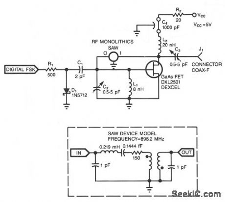
Adding a diode, a resistor, and a capacitor to the SAW (surface-acoustic-wave) oscillator allows you to use the oscillator in FSK (frequency-shift-keying) applications. D1, R1, and C1 form a simple diode switch in which D1 shunts C1 to ground. When the digital FSK input to R1 is low, D1 is off, and the small junction capacitance of D1 couples C1 to ground. A high FSK signal causes current to flow through R1 and D1.D1's dynamic impedance is small when it is in forward conduction. Therefore, C1 sees a lower impedance path to ground. Thus, the FSK input effectively switches C1 in and out of the oscillator's circuit.
When C1 is in the circuit-digital FSK is high-it pulls the frequency of the circuit slightly lower because of the additional phase shift C1 introduces at the GaGs FET gate terminal (available from: Dexcel, Div. of Gould, Santa Clara, CA). The SAW device (available from: RF Monolithics, Dallas, TX) restricts the amount of frequency shifting-usually less than 20 ppm for a high-Q SAW device.
The oscillator shown produces a center frequency of 896.2 MHz with an FSK deviation of 17 kHz when you drive the FSK input with a 0 to 5 V signal. The frequency also depends on L1 and C2.
Reprinted Url Of This Article:
http://www.seekic.com/circuit_diagram/Basic_Circuit/SAW_SOCILLATOR_MODULATOR.html
Print this Page | Comments | Reading(3)

Article Categories
power supply circuit
Amplifier Circuit
Basic Circuit
LED and Light Circuit
Sensor Circuit
Signal Processing
Electrical Equipment Circuit
Control Circuit
Remote Control Circuit
A/D-D/A Converter Circuit
Audio Circuit
Measuring and Test Circuit
Communication Circuit
Computer-Related Circuit
555 Circuit
Automotive Circuit
Repairing Circuit
Code: