Basic Circuit
SAWTOOTH_CONVERTER
Published:2009/7/10 1:30:00 Author:May | From:SeekIC

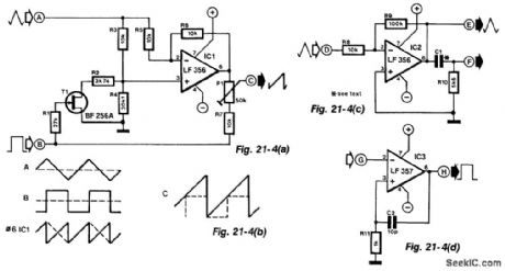
Simple function generators normally provide sinusoidal, rectangular, and triangular waveforms, but seldom a sawtooth. The circuit in Fig. 21-4(a) derives a sawtooth signal from a rectangular and triangular signal. Its quality depends on the linearity of the triangular signal, the slope of the edges of the rectangular signal and the phase relationship between the rectangular and triangular signals.
The conversion is carried out in IC1. Whether the triangular signal at input A is converted or not by IC1 depends on the state of T1. This FET is controlled by the rectangular signal at input B.
The signal at the output of the op amp is a sawtooth (see Fig. 21-4(b)) whose trailing edge is inverted. The frequency of this signal is double that of the input signals.
If in this state, the dc level of each inverted edge is raised sufficiently to make the lower level of that edge coincide with the higher level of the preceding edge, a sawtooth signal of the same frequency (but double the peak value of the input signals) is obtained. The dc level is raised by adding input B to the output of IC1 via R7 and P1. The preset should preferably be a multiturn type. Resistors R2 and R4 are 1% types.
If a rectangular signal is not available, or if its peak value is too small, the auxiliary circuits (shown in Figs. 21-4(c) and 21-4(d)) will be found useful. Figure 21-4(g) amplifies the triangular input at A by 10. Differentiating network C1/R10 derives rectangular pulses from the amplified triangular signal and these are available at F.
The pulses at F are shaped by the circuit in Fig. 21-4(d) to rectangular signals that have the same peak value as the supply voltage. Capacitor C2 increases the slope of the edge; it can be omitted for low-frequency signals.
The converter provides sawtooth signals over the frequency range of 15 Hz to 15 kHz. If the auxiliary circuits are used, capacitor C1 must be compatible with the frequency of the sawtooth signal (its value lies between 2 nF and 100 pF). The supply for all circuits can be between ±10 V and ±15V. Each op amp draws a current of 4 to 6 mA.
Reprinted Url Of This Article:
http://www.seekic.com/circuit_diagram/Basic_Circuit/SAWTOOTH_CONVERTER.html
Print this Page | Comments | Reading(3)

Article Categories
power supply circuit
Amplifier Circuit
Basic Circuit
LED and Light Circuit
Sensor Circuit
Signal Processing
Electrical Equipment Circuit
Control Circuit
Remote Control Circuit
A/D-D/A Converter Circuit
Audio Circuit
Measuring and Test Circuit
Communication Circuit
Computer-Related Circuit
555 Circuit
Automotive Circuit
Repairing Circuit
Code: