Basic Circuit
SAFETY_FLARE
Published:2009/7/6 20:04:00 Author:May | From:SeekIC


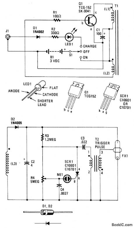
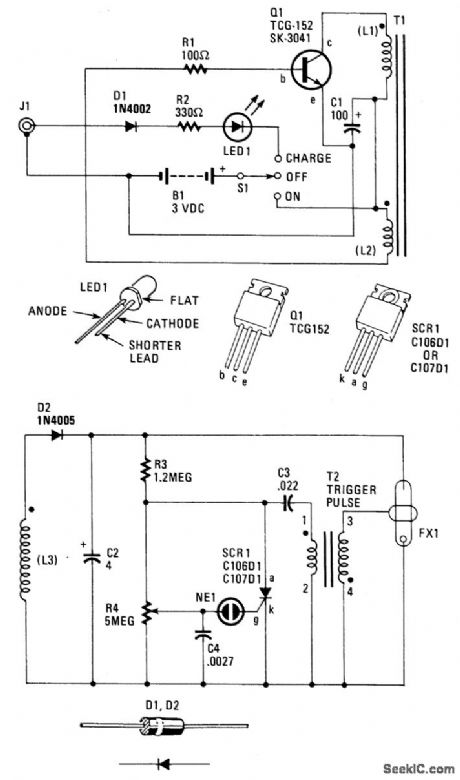
When 51 is on, power is applied to an oscillator composed of Q1, R1, C1, L1, and L2. Coil L1 is the primary winding of T1, and L2 is the feedback winding. When Q1 turns on, its collector current saturates T1's ferrite core. That, in turn, removes the base drive to Q1 through L2. Transistor Q1 then turns off. As the field around L1 and L2 decays, Q1 will eventually turn on again, and the cycle repeats over, and over.Transformer T1 is a step-up, ferritecore, potted-type unit whose secondary;winding (L3) output is rectified by D2 and filtered by C2. That capacitor charges up to around 250 to 300 volts, which is applied to the resistor divider composed of R3 and R4, along with the flash tube FX1.Capacitors C3 and C4 will charge up to around 200 and 100 volts, through R3 and R4, respectively. Flash rate is adjustable via R4. When the charge on C4 gets to around 100 volts, neon lamp NE1 fires discharging C4 into the gate circuit of silicon control rectifier SCR1. The SCR1 turns on discharging C3 into the primary winding of trigger-pulse transformer T2, Transformer T2 is another step-up, pulse-type unit providing an output of around 4 kW across transformer T2's secondary winding.The xenon gas inside FX1 is ionized and a bright flash is emitted. Finally, C3 quickly discharges through L4, and the cycle repeats over, and over.
Reprinted Url Of This Article:
http://www.seekic.com/circuit_diagram/Basic_Circuit/SAFETY_FLARE.html
Print this Page | Comments | Reading(3)

Article Categories
power supply circuit
Amplifier Circuit
Basic Circuit
LED and Light Circuit
Sensor Circuit
Signal Processing
Electrical Equipment Circuit
Control Circuit
Remote Control Circuit
A/D-D/A Converter Circuit
Audio Circuit
Measuring and Test Circuit
Communication Circuit
Computer-Related Circuit
555 Circuit
Automotive Circuit
Repairing Circuit
Code: