Basic Circuit
REMOTE_TELEPHONE_RINGER
Published:2009/7/7 22:09:00 Author:May | From:SeekIC

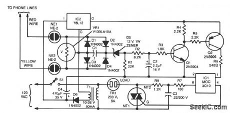
The two neon bulbs will light when more than 100 V is across the ringing circuit. The bulbs provide line isolation between the unit and the telephone line. Finally, they act as a voltage divider for the bridge rectifier made up of D1 through D4. That voltage divider creates a positive voltage that is then applied through D5, is filtered by R2, R3, and C2, and causes Q1 and Q2 to conduct. When that happens, triac TR1 is fired through the optical coupler IC1; this turns on the triac, which applies 110 Vac to the load.
Reprinted Url Of This Article:
http://www.seekic.com/circuit_diagram/Basic_Circuit/REMOTE_TELEPHONE_RINGER.html
Print this Page | Comments | Reading(3)

Article Categories
power supply circuit
Amplifier Circuit
Basic Circuit
LED and Light Circuit
Sensor Circuit
Signal Processing
Electrical Equipment Circuit
Control Circuit
Remote Control Circuit
A/D-D/A Converter Circuit
Audio Circuit
Measuring and Test Circuit
Communication Circuit
Computer-Related Circuit
555 Circuit
Automotive Circuit
Repairing Circuit
Code: