Basic Circuit
RECTANGULAR_TRIANGULAR_WAVEFORM_CONVERTER
Published:2009/7/10 1:44:00 Author:May | From:SeekIC

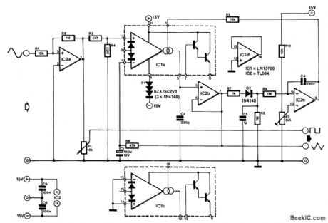
Many function generators are based on a rectangular waveform generator that consists or a Schmitt trigger and integrator. The triangular signal produced by the integrator is then used to form a sinusoidal signal with the aid of a diode network. The converter presented here works the other way around. It con-verts the output of a good-quality sine-wave oscillator into a rectangular and a triangular siant.
The sinusoidal siinal is converted into a rectangular signal by IC2A. Because the output of this gate varies between - 15 V and + 15 V, it is reduced to a value that is suitable for integration by potential divider R3/R4. It is then integrated by transconductance amplifier IC1A and C2. The amplifier has a current output that is controlled by the current through pin 1. The output therefore behaves as a resistance, with which it is possible to influence the integration time.
The voltage across C2 is available in buffered form at the output of impedance inverter IC2B; this is the triangular signal. The amplitude of this signal is compared with a voltage set by P2 and the difference between these voltages, which is the output of IC2C, is applied to the current source at the output of IC1 via R5. This arrangement ensures that the level of the output voltage is virtually independent of the frequency of the rectangular signal or of the sinusoidal input.
One problem with a precision integration is its being affected by offset voltages and bias currents. Feedback loop R6/C1 ensures that the output follows the potential across R4 accurately. However, tiny deviations might be caused by the bias current in circuit IC1, which is not greater than 8 μA at 70℃.The time constant R6/C1 is large for a purpose: to ensure that the triangular signal, even at low fre-quencies, cannot affect the waveform of the signal to be integrated-the rectangular shape must be retained. The converter can process signals at frequencies from 6 Hz (where the amplitude is not affected) to 60 kHz (where the amplitude is reached by 10%).
Because of the long time constants, the time taken for the recovery of the amplitude of the triangular signal at frequencies above 1 kHz is rather long. The peak value of this signal should be set to 1 V.
Diode D1 is a so-called sfaGa'slot-three diodes in one package. It might be replaced by three discrete type 1N4148 diodes. The current drawn by the converter is of the order of 9 mA.
Reprinted Url Of This Article:
http://www.seekic.com/circuit_diagram/Basic_Circuit/RECTANGULAR_TRIANGULAR_WAVEFORM_CONVERTER.html
Print this Page | Comments | Reading(3)

Article Categories
power supply circuit
Amplifier Circuit
Basic Circuit
LED and Light Circuit
Sensor Circuit
Signal Processing
Electrical Equipment Circuit
Control Circuit
Remote Control Circuit
A/D-D/A Converter Circuit
Audio Circuit
Measuring and Test Circuit
Communication Circuit
Computer-Related Circuit
555 Circuit
Automotive Circuit
Repairing Circuit
Code: