Basic Circuit
QUADRATURE_DETECTOR_DESIGN
Published:2009/7/13 3:51:00 Author:May | From:SeekIC

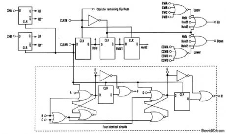
One common electrical requirement when dealing with motion control is to monitor the angular position of a rotating object.Quite often, an optical encoder is attached to a rotating shaft, and the encoder's quadrature outputs provide angular displacement information. The key is to turn those quadrature signals into clock pulses, and then into a displacement count that's useful for your application. This circuit requires a reset as well as a clock for sampling the input data. The clock frequency needs to be adjusted to guarantee at least one rising clock edge for each input state change. The circuit takes a set of quadrature signals (CHA, CHB), samples them with CLKIN, and generates output clock pulses (UP or DN) for each input state change. The up/down output clock pulses then can be fed directly into 74XX193 counters as the up and down clocks. If CLKIN is synchronized to external timing, the 193 ripple counter's output can be latched out of phase with the updates to ensure stable counter values. The timing diagram shows the internal functionality of the design. Intervals 1 to 5 illustrate the reset function, which blanks startup instability conditions.Intervals 5 through 12 show timing for a jitter pulse that's been sampled. Interval13 depicts a jitter pulse that missed being sampled and, therefore, caused no change in the output. The remaining intervals illustrate complete cycles for each direction of motion.
Reprinted Url Of This Article:
http://www.seekic.com/circuit_diagram/Basic_Circuit/QUADRATURE_DETECTOR_DESIGN.html
Print this Page | Comments | Reading(3)

Article Categories
power supply circuit
Amplifier Circuit
Basic Circuit
LED and Light Circuit
Sensor Circuit
Signal Processing
Electrical Equipment Circuit
Control Circuit
Remote Control Circuit
A/D-D/A Converter Circuit
Audio Circuit
Measuring and Test Circuit
Communication Circuit
Computer-Related Circuit
555 Circuit
Automotive Circuit
Repairing Circuit
Code: