Basic Circuit
QRP_SWR_BRIDGE
Published:2009/7/7 23:08:00 Author:May | From:SeekIC

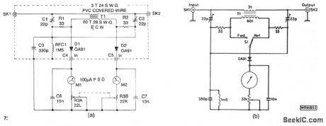
The design shown is a simple unit for QRP operation on all authorized frequencies up to 30 MHz, based on a toroidal transformer T1. The secondary winding of T1 samples a small amount of rf power, both forward and reflected, which is divided by the bridge circuit and rectified by diodes D1and D2. Forward and reflected readings are obtained simultaneously on the two meters Ml and M2, and the bridge is matched and balanced at the required load impedance by C1 and C2. See Fig. 56-9b for an alternative, less expensive, single meter version. The bridge also measure forward power.
Reprinted Url Of This Article:
http://www.seekic.com/circuit_diagram/Basic_Circuit/QRP_SWR_BRIDGE.html
Print this Page | Comments | Reading(3)

Article Categories
power supply circuit
Amplifier Circuit
Basic Circuit
LED and Light Circuit
Sensor Circuit
Signal Processing
Electrical Equipment Circuit
Control Circuit
Remote Control Circuit
A/D-D/A Converter Circuit
Audio Circuit
Measuring and Test Circuit
Communication Circuit
Computer-Related Circuit
555 Circuit
Automotive Circuit
Repairing Circuit
Code: