Basic Circuit
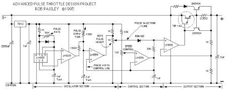
Pulse Type Throttle Schematic
Published:2013/6/25 22:00:00 Author:muriel | Keyword: Pulse Type , Throttle Schematic | From:SeekIC

The next schematic is for an advanced type of pulse throttle. Simply put, as the output voltage is increased by the 10K pot, a pulse is injected onto the the control voltage at the PLUS input terminal of the second LM358 OpAmp. As the control voltage increases the width of the pulse is also increased.The height of the pulse is adjusted so that at some point it is overtaken by the output of the first OpAmp section. From this point on the output from the throttle is pure DC
The duration of the pulse is adjusted so that it is at approximately 50% when the pulse voltage is overtaken by the output control voltage.
The pulse rate can also be varied but whenever the rate is adjusted the other variables of the oscillator will be thrown off and all would have to be reset.
To properly set up this particular throttle an oscilloscope is required.
Overall this particular throttle did not perform as I had hoped it might, but seemed to work well for locomotives with good quality motors.
Reprinted Url Of This Article:
http://www.seekic.com/circuit_diagram/Basic_Circuit/Pulse_Type_Throttle_Schematic.html
Print this Page | Comments | Reading(3)

Article Categories
power supply circuit
Amplifier Circuit
Basic Circuit
LED and Light Circuit
Sensor Circuit
Signal Processing
Electrical Equipment Circuit
Control Circuit
Remote Control Circuit
A/D-D/A Converter Circuit
Audio Circuit
Measuring and Test Circuit
Communication Circuit
Computer-Related Circuit
555 Circuit
Automotive Circuit
Repairing Circuit
Code: