Basic Circuit
Precision rectifier circuit with integral circuit
Published:2012/9/23 21:14:00 Author:Ecco | Keyword: Precision rectifier , integral circuit | From:SeekIC

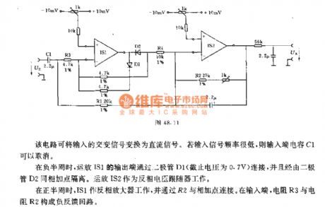
The circuit can switch input alternating signal to DC signal. If the input signal frequency is low, the input-terminal capacitor C1 can be canceled.In the negative half cycle, the output terminal of op amp IS1 is connected by diode D1 ( off voltage is 0.7V) and isolated from the same summing point via the diode D2. Op amp IS2 works as the inverting voltage follower.In the positive half cycle, IS1 works as an inverting amplifier and is connected to the summing point by R2. At the input terminal, the resistor R3 and resistor R2 constitute a negative feedback loop.
Reprinted Url Of This Article:
http://www.seekic.com/circuit_diagram/Basic_Circuit/Precision_rectifier_circuit_with_integral_circuit.html
Print this Page | Comments | Reading(3)

Article Categories
power supply circuit
Amplifier Circuit
Basic Circuit
LED and Light Circuit
Sensor Circuit
Signal Processing
Electrical Equipment Circuit
Control Circuit
Remote Control Circuit
A/D-D/A Converter Circuit
Audio Circuit
Measuring and Test Circuit
Communication Circuit
Computer-Related Circuit
555 Circuit
Automotive Circuit
Repairing Circuit
Code: