Basic Circuit
Power_on_reset_generator
Published:2009/7/24 12:41:00 Author:Jessie | From:SeekIC

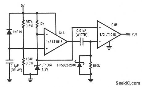
This circuit uses both sections of an LT1018 to reset a digital system after supply turn-on. When supply power is applied, the 5-V rail comes up. The LT1004 clamps at 1.2 V and the C1A noninverting input ramps at a time constant that is determined by the 0.05% resistors and the 0.1-μF capacitor. When the C1A noninverting input ramps beyond the LT1004 potential, the C1A output goes high and delivers a differentiated pulse to the C1B inverting input. The C1B output goes low for a period that is determined by the 0.01-μF/680-kΩ differentiator. The 1N914 gives quick reset for the 0.1-μF capacitor, and the Schottky diode clips differentiator-caused negative voltages at the C1B input. The turn-on threshold (4.8 V in this case) is set by the ratio of the 0.5% resistors. The output-pulse delay time is controlled by the 0.1-μF capacitor, which can be varied. Similarly, the RC combination at C1B sets output pulse width, and can be varied. The LT1018 1.2-V minimum supply voltage prevents spurious output during supply power-up. Linear Technology, Linear Applications Handbook, 1990, p. AN31-10.
Reprinted Url Of This Article:
http://www.seekic.com/circuit_diagram/Basic_Circuit/Power_on_reset_generator.html
Print this Page | Comments | Reading(3)

Article Categories
power supply circuit
Amplifier Circuit
Basic Circuit
LED and Light Circuit
Sensor Circuit
Signal Processing
Electrical Equipment Circuit
Control Circuit
Remote Control Circuit
A/D-D/A Converter Circuit
Audio Circuit
Measuring and Test Circuit
Communication Circuit
Computer-Related Circuit
555 Circuit
Automotive Circuit
Repairing Circuit
Code: