Basic Circuit
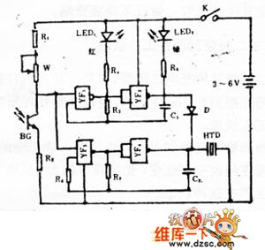
Photoelectric photometry switch circuit diagram
Published:2011/6/27 4:56:00 Author:Ecco | Keyword: Photoelectric, photometry, switch | From:SeekIC

After the power switch K is turned on, beat pulse generator and audio oscillator pulse will begin to work. In the part of beat pulse generator, YF1 and YF2 output pulses have opposite polarity. With the output of oscillator pulse, light emitting diodes LED1 and LED2 alternately emit light, and the flash cycle is determined by R3, C1 values; in the part of audio oscillator, the oscillation voltage is determined by the output end of YF4, then HTD issues single-frequency sound, and the audio pulse frequency is established by the R7, C2 values.
Reprinted Url Of This Article:
http://www.seekic.com/circuit_diagram/Basic_Circuit/Photoelectric_photometry_switch_circuit_diagram.html
Print this Page | Comments | Reading(3)

Article Categories
power supply circuit
Amplifier Circuit
Basic Circuit
LED and Light Circuit
Sensor Circuit
Signal Processing
Electrical Equipment Circuit
Control Circuit
Remote Control Circuit
A/D-D/A Converter Circuit
Audio Circuit
Measuring and Test Circuit
Communication Circuit
Computer-Related Circuit
555 Circuit
Automotive Circuit
Repairing Circuit
Code: