Basic Circuit
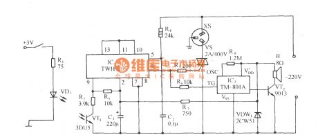
Photocoupling zero-crossing control socket circuit using TWH9205
Published:2012/9/18 2:34:00 Author:Ecco | Keyword: Photocoupling , zero-crossing control , socket | From:SeekIC

As shown in Figure, the circuit consists of zero-crossing driving switch, photoelectric coupling input circuit, the thyristor control circuit and sound circuit. The phototransistor switching circuit in FIG is connected to the inverting input terminal ( 9 feet) of the differential switching amplifier TWH9205, when the terminal voltage is lower than the clamping voltage of the positive-phase input terminal, i.e., when the phototube 3DU5 is irradiated by light, only when AC os over zero, TWH9205 outputs high to drive SCR VS conduction, then socket XS gets electric, and the electrical equipments connected to XS operate. VS can use 1 ~ 500A triac according to the size of the electrical load power.
Reprinted Url Of This Article:
http://www.seekic.com/circuit_diagram/Basic_Circuit/Photocoupling_zero_crossing_control_socket_circuit_using_TWH9205.html
Print this Page | Comments | Reading(3)

Article Categories
power supply circuit
Amplifier Circuit
Basic Circuit
LED and Light Circuit
Sensor Circuit
Signal Processing
Electrical Equipment Circuit
Control Circuit
Remote Control Circuit
A/D-D/A Converter Circuit
Audio Circuit
Measuring and Test Circuit
Communication Circuit
Computer-Related Circuit
555 Circuit
Automotive Circuit
Repairing Circuit
Code: