Basic Circuit
Partial voltage type negative feedback bias circuit
Published:2011/6/27 21:36:00 Author:Christina | Keyword: Partial voltage, negative feedback, bias circuit | From:SeekIC
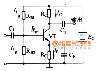
This circuit is designed as one kind of bias circuit, the typical circuit is as shown in the figure. In this circuit, the transistor emitter is connected with the RE, and the base electrode is connected with the RB1 and RB2.
Figure Partial voltage type negative feedback bias circuit
The partial voltage type negative feedback bias circuit has two kinds of stable effects:
1. Through the partial voltage of the base resistance RB1 and RB2, this relation is founding:
I2=I1-IB≈I1
UB=Ec-I1RB1
UB=I2xRB2
2.If you add the RE in this circuit, this circuit will have the function of current negative feedback temperature compensation.
Because of the two stable functions, this partial voltage type negative feedback bias circuit has good stable function.
Reprinted Url Of This Article:
http://www.seekic.com/circuit_diagram/Basic_Circuit/Partial_voltage_type_negative_feedback_bias_circuit.html
Print this Page | Comments | Reading(3)

Article Categories
power supply circuit
Amplifier Circuit
Basic Circuit
LED and Light Circuit
Sensor Circuit
Signal Processing
Electrical Equipment Circuit
Control Circuit
Remote Control Circuit
A/D-D/A Converter Circuit
Audio Circuit
Measuring and Test Circuit
Communication Circuit
Computer-Related Circuit
555 Circuit
Automotive Circuit
Repairing Circuit
Code: