Basic Circuit
PULSE_EDGE_SELECTOR
Published:2009/7/15 5:37:00 Author:Jessie | From:SeekIC
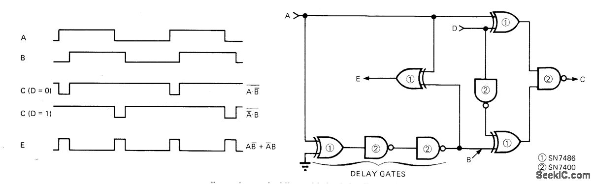
Two quad TTL packages form simple circuit that generates output pulse at C as function of either leading or trailing edge of input pulse at A, depending on logic level at terminal D. Additional output at E supplies pulses coinciding with both leading and trailing edges of input, independently of logic level at D. Maximum input frequency is 10 MHz, and edge pulses are about 35 ns wide. IC1 is quad two-input EXCLUSIVE-OR gate, and IC2 is quad two-input NAND gate.-C. F. Reeves, A Programmable Pulse-Edge Selector, EDN Magazine, April 20, 1973, p 85 and 87.
Reprinted Url Of This Article:
http://www.seekic.com/circuit_diagram/Basic_Circuit/PULSE_EDGE_SELECTOR.html
Print this Page | Comments | Reading(3)

Article Categories
power supply circuit
Amplifier Circuit
Basic Circuit
LED and Light Circuit
Sensor Circuit
Signal Processing
Electrical Equipment Circuit
Control Circuit
Remote Control Circuit
A/D-D/A Converter Circuit
Audio Circuit
Measuring and Test Circuit
Communication Circuit
Computer-Related Circuit
555 Circuit
Automotive Circuit
Repairing Circuit
Code: