Basic Circuit
PRINTER_PORT_D_A_CONVERTER
Published:2009/7/12 20:58:00 Author:May | From:SeekIC

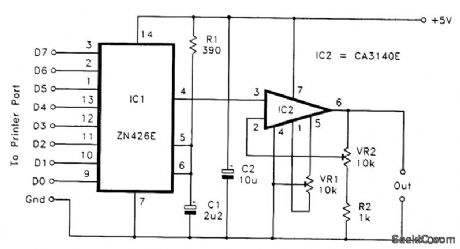
Where eight latching outputs are available, the Ferranti 2N426E probably represents the simplest means of providing an analog output. The figure shows the circuit diagram for a PC analog output port based on this chip. The full-scale output voltage is equal to the reference voltage fed to pin 5. This terminal can be fed from an external reference voltage of up to 3 V, but, in most cases, the built-in 2.55-V reference is perfectly adequate. The output voltage from IC1 (in volts) is equal to the value written to the printer port multiplied by 0.001. In most practical applications, this output-voltage range will have to be modified using an amplifier or an attenuator. In virtually all cases it will be a small amount of amplification that is required. This is the purpose of IC2, which also provides output buffering. The noninverting-mode amplifier IC2 can have its closed-loop voltage gain varied from unity to about 11 times by means of preset VR2.The maxinum output voltage of IC2 is about 2 V less than its supply potential (about 3 V) if it is powered from a 5-V supply. Therefore, maximum output voltages of more than 3 V require IC2 to be powered from a higher supply potential of up to about 30 V. This means using a separate supply for IC2 because the converter circuit must be powered from a 5-V supply. If preset VR1 is included, the best way to find the correct setting is to first write a low value to the port and adjust VR1 for the correct output voltage. Then write a high value to the port and adjust VR2 for the appropriate output voltage. Repeat this process a few times until no further adjustment is needed. If VE1 is omitted, write a value of 255 to the port and then adjust VR2 for the required maximum output voltage. Reasonable accuracy should then be obtained over the full range of output voltages.Using GW BASIC, it is just a matter of writing the values to the appropriate address using the OUT command. For example, OUT &H378,123 would write a value of 123 to a digital-to-analog converter connected to printer port LPT1.
Reprinted Url Of This Article:
http://www.seekic.com/circuit_diagram/Basic_Circuit/PRINTER_PORT_D_A_CONVERTER.html
Print this Page | Comments | Reading(3)

Article Categories
power supply circuit
Amplifier Circuit
Basic Circuit
LED and Light Circuit
Sensor Circuit
Signal Processing
Electrical Equipment Circuit
Control Circuit
Remote Control Circuit
A/D-D/A Converter Circuit
Audio Circuit
Measuring and Test Circuit
Communication Circuit
Computer-Related Circuit
555 Circuit
Automotive Circuit
Repairing Circuit
Code: