Basic Circuit
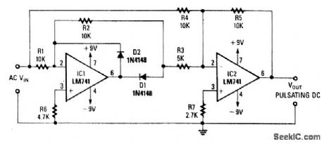
PRECISION_FULL_WAVE_RECTFIER
Published:2009/7/9 2:45:00 Author:May | From:SeekIC

Using two op amps, this circuit produces a full-wave rectified version of the input signal. Op amp IC1 inverts the negative-going signal, but because of D2, it stays near zero. IC2 produces a positive-going sig-nal. For positive-going signals, IC1 produces a negative output through D1 to IC2, where it is combined with positive VIN from R4/R5. At the summing junction of IC2, the negative output of IC1 is doubled and inverted via IC2, R3, and R5 to produce + V0UT. This is summed with negative output of IC1 to produce + V0UT.
Reprinted Url Of This Article:
http://www.seekic.com/circuit_diagram/Basic_Circuit/PRECISION_FULL_WAVE_RECTFIER.html
Print this Page | Comments | Reading(3)

Article Categories
power supply circuit
Amplifier Circuit
Basic Circuit
LED and Light Circuit
Sensor Circuit
Signal Processing
Electrical Equipment Circuit
Control Circuit
Remote Control Circuit
A/D-D/A Converter Circuit
Audio Circuit
Measuring and Test Circuit
Communication Circuit
Computer-Related Circuit
555 Circuit
Automotive Circuit
Repairing Circuit
Code: