Basic Circuit
POWER_SAVING_INTERMITTENT_CONVERTER
Published:2009/7/9 23:58:00 Author:May | From:SeekIC

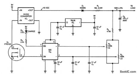
This circuit switches its dc/dc converter, IC1, off whenever the large filter capacitor, C6, has sufficient charge to power the load. This particular circuit uses a dc/dc converter that produces 115 Vdc from a 9-Vdc input; you can tailor the circuit to suit other converters. The heart of the circuit is a 555 timer configured as a dual-limit comparator. Thus, the 555 turns the converter on or off, depending on the voltage across CG. The 555's complementary output lights the charge LED when the FET is on.
Initially, the voltage on CG is zero, and the 555's output turns on the FET, Q1, in turn, enabling the converter to run, which charges C6. When the voltage on the capacitor reaches the value set by R3, the 555 turns the converter off. Then, C6 slowly discharges into the combined load of the voltage divider (R2, R3, and R4) and the reverse-biased blocking diode, D1.
When the voltage falls below 1/3 VCC, the 555 restarts the dc/dc converter. If this circuit powers a load that periodically goes into a zero-power, shutdown mode, the 555 switches the dc/dc converter on full time whenever the load kicks in.
When the supply voltage falls below 7.5 V, the output of the converter is no longer high enough to charge, the LED doesn't light. The circuit uses 205 mA when the converter is on and 10 mA when the converter is off. The duty cycle comprises a 5-s ON period, a 150-s OFF period, and it represents a 92% power reduction. You can further reduce power consumption by removing the charge LED and using a CMOS 555 and a CMOS 78LO5 regulator.
Reprinted Url Of This Article:
http://www.seekic.com/circuit_diagram/Basic_Circuit/POWER_SAVING_INTERMITTENT_CONVERTER.html
Print this Page | Comments | Reading(3)

Article Categories
power supply circuit
Amplifier Circuit
Basic Circuit
LED and Light Circuit
Sensor Circuit
Signal Processing
Electrical Equipment Circuit
Control Circuit
Remote Control Circuit
A/D-D/A Converter Circuit
Audio Circuit
Measuring and Test Circuit
Communication Circuit
Computer-Related Circuit
555 Circuit
Automotive Circuit
Repairing Circuit
Code: