Basic Circuit
PHONE_IN_USEINDICATOR
Published:2009/7/14 2:52:00 Author:May | From:SeekIC

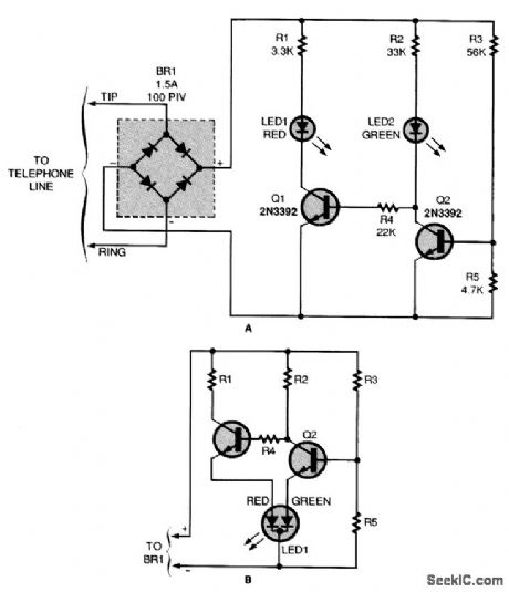
Tired of having your phone calls interrupted by others picking up the receiver? This circuit (A) will show others when the phone is in use. If you would like to experiment with a tricolor LED, check out the optional schematic (B).
When all telephones are on-hook, Q2's base is turned on by a voltage-divider circuit, consisting of R3 and R5. (The value shown for R5 causes the device to switch over at about 9 V; it can be changed to facilitate other voltage levels.) Transistor Q2 allows current to flow through R2 and LED2, indicating that the phone line is not in use. It also effectively grounds the base of Q1 and forces LED1 to remain off. When the voltage drops because a telephone goes off-hook, Q2 stops con-ducting, which allows a little current to flow from R2, LED2, and R4 to Q1's base. When that occurs, Q1 conducts, energizing LED1 and LED2 is deprived of sufficient current to glow. The bridge rectifier compensates for a possible reversal between the tip and ring wires, and rectifies the ring signal.
Reprinted Url Of This Article:
http://www.seekic.com/circuit_diagram/Basic_Circuit/PHONE_IN_USEINDICATOR.html
Print this Page | Comments | Reading(3)

Article Categories
power supply circuit
Amplifier Circuit
Basic Circuit
LED and Light Circuit
Sensor Circuit
Signal Processing
Electrical Equipment Circuit
Control Circuit
Remote Control Circuit
A/D-D/A Converter Circuit
Audio Circuit
Measuring and Test Circuit
Communication Circuit
Computer-Related Circuit
555 Circuit
Automotive Circuit
Repairing Circuit
Code: