Basic Circuit
PHASE_SELECTOR_PHASE_DETECTOR_SYNCHRONOUS_RECTIFIER_BALANCED_MODULATOR
Published:2009/7/9 2:12:00 Author:May | From:SeekIC


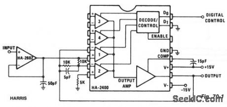
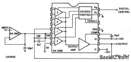
This circuit passes the input signal at unity gain, either unchanged or inverted, depending on the digital control input. A buffered input is shown, since low-source impedance is essential. Gain can be added by modifications to the feedback networks. Signals up to 100 kHz can be handled with 20.0-V pk-pk, output.The circuit becomes a phase detector when driving the digital control input with a reference phase at the same frequency as the input signal; the average dc output is proportional to the phase difference, with 0 V at +90°. By connecting the output to a comparator, which in turn drives the digital control, a synchronous full-wave rectifier is formed. With a low-frequency input signal and a high-frequency digital control signal, a balanced (suppressed carrier) modulator is formed.
Reprinted Url Of This Article:
http://www.seekic.com/circuit_diagram/Basic_Circuit/PHASE_SELECTOR_PHASE_DETECTOR_SYNCHRONOUS_RECTIFIER_BALANCED_MODULATOR.html
Print this Page | Comments | Reading(3)

Article Categories
power supply circuit
Amplifier Circuit
Basic Circuit
LED and Light Circuit
Sensor Circuit
Signal Processing
Electrical Equipment Circuit
Control Circuit
Remote Control Circuit
A/D-D/A Converter Circuit
Audio Circuit
Measuring and Test Circuit
Communication Circuit
Computer-Related Circuit
555 Circuit
Automotive Circuit
Repairing Circuit
Code: