© 2008-2012 SeekIC.com Corp.All Rights Reserved.
Basic Circuit
OPTICAL_SENSOR_TO_TTL_INTERFACE
Published:2009/7/7 21:17:00 Author:May | From:SeekIC

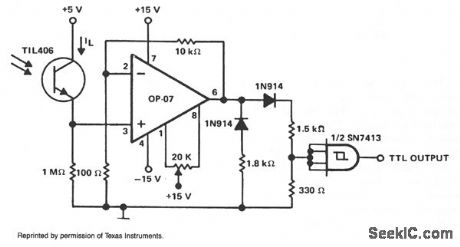
This circuit is designed to detect a low light level at the sensor, amplify the signal, and provide a TTL-level output. When the optical sensor detects low-level light, on condition, its output is small and must be amplified. An amp with very low input bias current and high input resistance must be used to detect the on condition. When sensor TlL406 is in the on condition, its output is assumed to be 250 nA (allowing a safety margin). This results in a 250-mV signal being applied to the noninverting input of amplifier OP-07.Because of the circuit configuration, the OP-07 provides a gain of 100 and its output is in positive saturation. The OP-07 output level is applied to a loading network that provides the basic TTL level.
Reprinted Url Of This Article:
http://www.seekic.com/circuit_diagram/Basic_Circuit/OPTICAL_SENSOR_TO_TTL_INTERFACE.html
Print this Page | Comments | Reading(3)

Article Categories
power supply circuit
Amplifier Circuit
Basic Circuit
LED and Light Circuit
Sensor Circuit
Signal Processing
Electrical Equipment Circuit
Control Circuit
Remote Control Circuit
A/D-D/A Converter Circuit
Audio Circuit
Measuring and Test Circuit
Communication Circuit
Computer-Related Circuit
555 Circuit
Automotive Circuit
Repairing Circuit
New published articles
Response in 12 hours

Code: