Basic Circuit
OPTICAL_DIRECTION_DISCRIMINATOR
Published:2009/6/24 3:53:00 Author:Jessie | From:SeekIC

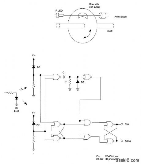
The very simple circuit uses only two CD4001 packages, i.e., eight NOR gates and operates in the following way: Pulse streams are fed to an RS flip flop generating an output waveform which has a small or large duty cycle depending on the direction of rotation. The same input pulses are also fed to a NOR gate, which adds the two pulse trains.
The rising edges of this waveform are used to produce short positive pulses from the circuit con-sisting of R1, C1, D3, and a NOR gate used as an inverter. This is used to sample the outputs of the flip flop to detect the direction of rotation. The output, whose duty cycle is large, forces the sampling NOR gate to generate a pulse train which sets (or resets) the second RS flip-flop continuously giv-ing a permanent indication of the direction of rotation.
Reprinted Url Of This Article:
http://www.seekic.com/circuit_diagram/Basic_Circuit/OPTICAL_DIRECTION_DISCRIMINATOR.html
Print this Page | Comments | Reading(3)

Article Categories
power supply circuit
Amplifier Circuit
Basic Circuit
LED and Light Circuit
Sensor Circuit
Signal Processing
Electrical Equipment Circuit
Control Circuit
Remote Control Circuit
A/D-D/A Converter Circuit
Audio Circuit
Measuring and Test Circuit
Communication Circuit
Computer-Related Circuit
555 Circuit
Automotive Circuit
Repairing Circuit
Code: