Basic Circuit
Motor vehicle steering flasher 2
Published:2011/7/29 3:05:00 Author:Ecco | Keyword: Motor vehicle , steering flasher | From:SeekIC

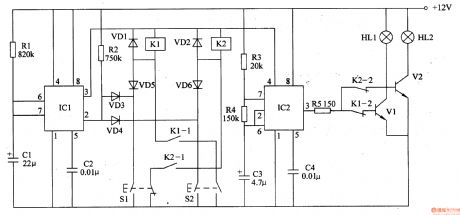
The motor vehicle steering flasher described in the example controls left and right turn signal by two control buttons respectively. Clicking the button will automatically turn on lights (one flash per second), it flashes about 20S then automatically turns off the power supply, thus avoiding the traffic accidents caused by forgetting to turn off lights.
The working principleThe motor vehicle steering flasher circuitis composed of monostable delay trigger, multivibrator and the trigger control circuit, it is shown as the chart 7-24.
Monostable circuitis composed of the time base trigger delay circuit ICl, resistors Rl, R2, capacitor Cl, C2.
Multivibrator integrated circuitis composed ofthe time base IC2, resistors R3, R4 and capacitors C3, C4.
Control circuit is composed of the control button Sl, S2, the relay Kl, K2, transistors Vl, V2 and diode VDl-VD6.
Component selection
Rl-R4 select the 1/4W metal film resistors or carbon film resistors; R5 selects the1W metal film resistor.
C uses the aluminium electrolytic capacitor with the voltage in 25V; C2 and C4 choose the monolithic capacitors or polyester capacitors.
Vl and V2 select 3DDl5 or DDO3 NPN silicon transistors.
Reprinted Url Of This Article:
http://www.seekic.com/circuit_diagram/Basic_Circuit/Motor_vehicle_steering_flasher_2.html
Print this Page | Comments | Reading(3)

Article Categories
power supply circuit
Amplifier Circuit
Basic Circuit
LED and Light Circuit
Sensor Circuit
Signal Processing
Electrical Equipment Circuit
Control Circuit
Remote Control Circuit
A/D-D/A Converter Circuit
Audio Circuit
Measuring and Test Circuit
Communication Circuit
Computer-Related Circuit
555 Circuit
Automotive Circuit
Repairing Circuit
Code: