Basic Circuit
Microprocessor_monitor
Published:2009/7/23 21:25:00 Author:Jessie | From:SeekIC


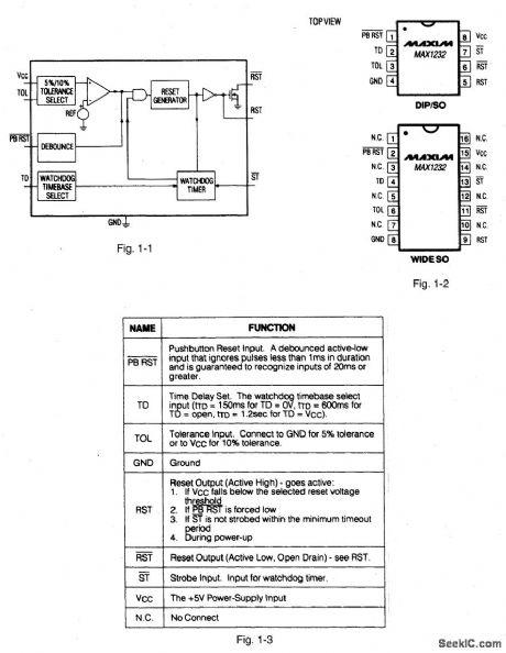
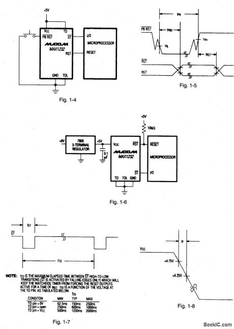
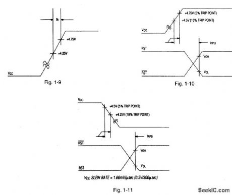
Figures 1-1, 1-2, and 1-3 show the block diagram, pin configuration and pin description, respectively, for the MAX1232. The IC is similar to that described for Figs. 1-K and 1-L, except that only '/to power is consumed. Figures 1-4 and 1-5 show the basic connections and waveforms, respectively, for the pushbutton reset.Figures 1-6 and 1-7 show the basic connections and waveforms, respectively, for watchdog timing. Notice that the software routine that strobes ST is critical. The code must be in a section of software that executes frequently enough so that the time between toggles is less than the watchdog timeout period, as shown in Fig. 1-7. Figures 1-8 and 1-9 show the power-down and power-up slew rate, respectively.Figures 1-10 and 1-11 show the VCC-detect reset-output delays. MAXIM NEW RELEASES DATA BOOK, 1992, P. 5-11, 5-14, 5-:5, 5-16.
Reprinted Url Of This Article:
http://www.seekic.com/circuit_diagram/Basic_Circuit/Microprocessor_monitor.html
Print this Page | Comments | Reading(3)

Article Categories
power supply circuit
Amplifier Circuit
Basic Circuit
LED and Light Circuit
Sensor Circuit
Signal Processing
Electrical Equipment Circuit
Control Circuit
Remote Control Circuit
A/D-D/A Converter Circuit
Audio Circuit
Measuring and Test Circuit
Communication Circuit
Computer-Related Circuit
555 Circuit
Automotive Circuit
Repairing Circuit
Code: