Basic Circuit
Microprocessor_interface_considerations
Published:2009/7/25 5:02:00 Author:Jessie | From:SeekIC


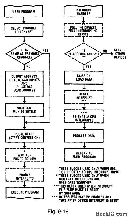
Figures 9-18 and 9-19 show flow charts for the interrupt-control and polled-I/O modes of ADC/microprocessor interface, respectively. Either interface can be used with the ADC0816/17, but the polled-I/O method usually requires fewer external components. With polled-I/O, the microprocessor (or CPU) periodically interrogates the ADC which looks like an I/O port to the CPU. With interrupt-control, the ADC appears as a memory and interrupts the microprocessor. From a simplified-design standpoint, the major concern is whether the EOC (end of conversion, Figi 9-3) should be polled by the microprocessor. Even though the actual timing of CPU read and write cycles varies, most microprocessors output the address and data (during write) onto the system buses. A certain time later, the read or write strobes go active for a specified time. The interface logic must detect the state of the address and data buses and initiate the action. For the ADC0816/17; these actions are: (1) load channel address, (2) start conversion, (3) detect EOC, and (4) read the resultant data. These functions are performed by decoding the read-write strobes, address, and data to form ALE and START pulses, then to detect EOC, and finally to read the data. NATIONAL SEMICONDUCTOR, APPLICATION NOTE 258, 1994, P. 605.
Reprinted Url Of This Article:
http://www.seekic.com/circuit_diagram/Basic_Circuit/Microprocessor_interface_considerations.html
Print this Page | Comments | Reading(3)

Article Categories
power supply circuit
Amplifier Circuit
Basic Circuit
LED and Light Circuit
Sensor Circuit
Signal Processing
Electrical Equipment Circuit
Control Circuit
Remote Control Circuit
A/D-D/A Converter Circuit
Audio Circuit
Measuring and Test Circuit
Communication Circuit
Computer-Related Circuit
555 Circuit
Automotive Circuit
Repairing Circuit
Code: