Basic Circuit
Medicinal automatic timing erythrocyte sedimentation rate shelf
Published:2011/6/24 8:17:00 Author:Nicole | Keyword: automatic timing, erythrocyte sedimentation rate, shelf | From:SeekIC

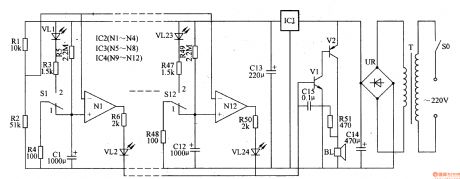
This medicinal automatic timing erythrocyte sedimentation rate shelf circuit is composed of power supply circuit, sound alarming circuit and timing circuit, it is shown in the figure 9-158.
The power supply circuit is made of power supply switch SO, power supply transformer T, rectifier quad UR, filter capacitor C13, C14 and three terminal regulator integrated circuit IC1.
The sound alarming circuit consists of transistors V1, V2, resistor R5, capacitor C13 and loudspeaker BL.
The 220V voltage is pressure released by T, it is rectificated by UR, it is filtered by C14, it is regulated voltage by IC1, one path provides IC2-IC4 with +12V work voltage, after divided voltage by R1, R2, the other path provides N1-N12's phase reversal input terminal with reference voltage.
Reprinted Url Of This Article:
http://www.seekic.com/circuit_diagram/Basic_Circuit/Medicinal_automatic_timing_erythrocyte_sedimentation_rate_shelf.html
Print this Page | Comments | Reading(3)

Article Categories
power supply circuit
Amplifier Circuit
Basic Circuit
LED and Light Circuit
Sensor Circuit
Signal Processing
Electrical Equipment Circuit
Control Circuit
Remote Control Circuit
A/D-D/A Converter Circuit
Audio Circuit
Measuring and Test Circuit
Communication Circuit
Computer-Related Circuit
555 Circuit
Automotive Circuit
Repairing Circuit
Code: