Basic Circuit
MONOSTABLE_OPERATION
Published:2009/7/7 6:28:00 Author:May | From:SeekIC

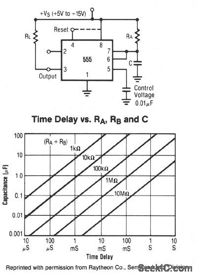
In this mode, the timer functions as a one shot. The external capacitor is initially held discharged by a transistor internal to the timer. Applying a negative trigger pulse to pin 2 sets the flip-flop, driving the output high, and releasing the short circuit across the external capacitor. The voltage across the capacitor increases with the time constant r = RAC to 2/3 VS, where the comparator resets the flip-flop and discharges the external capacitor. The output is now in the low state.Circuit triggering takes place when the negative-going trigger pulse reaches 1/3 VS; the circuit stays in the output high state until the set time elapses. The time the output remains in the high state is 1.1 RAC and can be determined by the graph. A negative pulse applied to pin 4 (reset) during the timing cycle will discharge the external capacitor and start the cycle over again beginning on the positive-going edge of the reset pulse. If reset function is not used, pin 4 should be connected to Vs to avoid false resetting.
Reprinted Url Of This Article:
http://www.seekic.com/circuit_diagram/Basic_Circuit/MONOSTABLE_OPERATION.html
Print this Page | Comments | Reading(3)

Article Categories
power supply circuit
Amplifier Circuit
Basic Circuit
LED and Light Circuit
Sensor Circuit
Signal Processing
Electrical Equipment Circuit
Control Circuit
Remote Control Circuit
A/D-D/A Converter Circuit
Audio Circuit
Measuring and Test Circuit
Communication Circuit
Computer-Related Circuit
555 Circuit
Automotive Circuit
Repairing Circuit
Code: