Basic Circuit
MODEL_ROCKET_LAUNCHER
Published:2009/7/1 20:56:00 Author:May | From:SeekIC

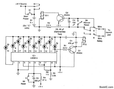
The circuit consists of the launch timer itself and an automatic-off timer. When power is applied to that IC, the countdown LED's sequence is on until they are all lit. When the last one LED1, is fully lit, transistor Q1 saturates, energizing RY2. When that happens, a circuit between the lantern battery at the launch pad and the nickel-chromium wire is completed; the wire heats up as before, and the rocket is launched. Resistor R4 and capacitor C3 determine the countdown timing; with the values shown it should be approximately 10 seconds. Resistors R3 and R5 set the LED brightness. Safety is of the utmost importance. That's the purpose of the second half of the circuit. When RY2 opens, the current flow to Q2 is disrupted. But, because of the presence of R2 and C4, the transistor remains saturated for about 3 seconds. After that, however, the transistor stops conducting and RY1 is de-energized. That cuts off the power to the rest of the circuit, and RY2 de-energizes again, breaking the circuit to the launch pad. Switch S3 is used to reset the countdown. Once that is done, pressing S1 starts the launch sequence; the rest is automatic. Switch S4 is used to latch RY1 manually if needed.
Reprinted Url Of This Article:
http://www.seekic.com/circuit_diagram/Basic_Circuit/MODEL_ROCKET_LAUNCHER.html
Print this Page | Comments | Reading(3)

Article Categories
power supply circuit
Amplifier Circuit
Basic Circuit
LED and Light Circuit
Sensor Circuit
Signal Processing
Electrical Equipment Circuit
Control Circuit
Remote Control Circuit
A/D-D/A Converter Circuit
Audio Circuit
Measuring and Test Circuit
Communication Circuit
Computer-Related Circuit
555 Circuit
Automotive Circuit
Repairing Circuit
Code: