Basic Circuit
MACHINE_VISION_ILLUMINATION_STABILIZER
Published:2009/7/1 1:13:00 Author:May | From:SeekIC

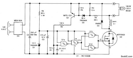
The combination of Q1, Q2 and U1 form a hysteresis oscillator to stabilize lamp illumination. In operation, full wave bridge D3 operates directly from the ac line to sup-ply unregulated dc to the lamp and also to the 10 V zener that provides power to the quad CMOS Schmitt trigger, U1. When the lamp supply exceeds 115 V, Q1 is turned ON, charging Ct through R2 to raise the input to Ula past the positive-going logic thresh-old. This drops the output voltage at Ulc and Uld, which drives the gate of Q2, turning it OFF. Current then decays through the lamp, L1 and D3 until the lamp voltage falls below 115 V, at which time Q1 turns OFF and the cycle repeats.
Reprinted Url Of This Article:
http://www.seekic.com/circuit_diagram/Basic_Circuit/MACHINE_VISION_ILLUMINATION_STABILIZER.html
Print this Page | Comments | Reading(3)

Article Categories
power supply circuit
Amplifier Circuit
Basic Circuit
LED and Light Circuit
Sensor Circuit
Signal Processing
Electrical Equipment Circuit
Control Circuit
Remote Control Circuit
A/D-D/A Converter Circuit
Audio Circuit
Measuring and Test Circuit
Communication Circuit
Computer-Related Circuit
555 Circuit
Automotive Circuit
Repairing Circuit
Code: