Basic Circuit
Low_cost_supervisory_circuit_with_battery_backup_30_V_33_V
Published:2009/7/23 21:38:00 Author:Jessie | From:SeekIC
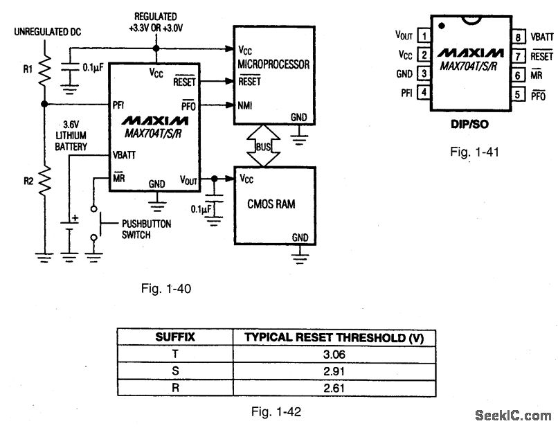
Figures 1-40 and 1-41 show a typical application circuit and pin configuration, respectively, for the MAXTO4T/S/R. The ICs are similar to that described for Figs.1-J through 1-M, but with generally lower cost, and for use with 3.0-V/3.3-V systems. The ICs have a 200-ms reset time delay, 50-μA quiescent current, 50-nA quiescent with battery backup, and a 1.25-V threshold detector for power-fail warning, low-battery detection, or for monitoring a supply other than 3.0 V or 3.3 V. The T, S, and R versions have different threshold levels, as shown in Fig. 1-42. MAXIM NEW RE[,EASES DATA Book, 1994, p 5-43.
Reprinted Url Of This Article:
http://www.seekic.com/circuit_diagram/Basic_Circuit/Low_cost_supervisory_circuit_with_battery_backup_30_V_33_V.html
Print this Page | Comments | Reading(3)

Article Categories
power supply circuit
Amplifier Circuit
Basic Circuit
LED and Light Circuit
Sensor Circuit
Signal Processing
Electrical Equipment Circuit
Control Circuit
Remote Control Circuit
A/D-D/A Converter Circuit
Audio Circuit
Measuring and Test Circuit
Communication Circuit
Computer-Related Circuit
555 Circuit
Automotive Circuit
Repairing Circuit
Code: