Basic Circuit
Low_cost_supervisory_circuit_with__3_V_monitoring
Published:2009/7/23 21:37:00 Author:Jessie | From:SeekIC

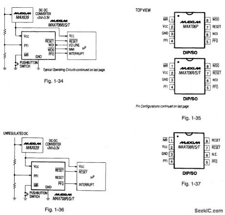
Figures 1-34 and 1-35 show a typical application circuit and pin configurations, respectively, for the MAX706P/R/S/T. Figures 1-36 and 1-37 show a typical application, circuit and pin configuration; respectively, for the MAX708R/S/T The ICs are similar to that described for Figs. 1-J through 1-M, but with the capability of monitoring +3-V supply levels. The ICs have a 200-ms reset pulse width, 100-pA quiescent current, a watchdog with 1.6-s timeout, and a 1.25-V threshold detector for power-fail warning, low-battery detection, or for monitoring supply levels in the +3-V to +5;V range. The difference among the MAX706R,S, and T is the reset-threshold levels, which are 2.63 V, 2.93 V and 3.08 V, respectively. All have active-low reset output signals. The MAX706P reset output is active-high with a 2.63-V threshold. The MAX708R/S/T are identical to the corresponding MAX706, except that the MAX708 series does not have a watchdog, but provides both RESET and RESET outputs. The watchdog is activated when the WDI input has not been toggled within 1,6 s. All of the ICs have an active-low manual reset.MAXIM HIGH-RELIABILITY DATA Book, 1993, P. 5-33, 5-34.
Reprinted Url Of This Article:
http://www.seekic.com/circuit_diagram/Basic_Circuit/Low_cost_supervisory_circuit_with__3_V_monitoring.html
Print this Page | Comments | Reading(3)

Article Categories
power supply circuit
Amplifier Circuit
Basic Circuit
LED and Light Circuit
Sensor Circuit
Signal Processing
Electrical Equipment Circuit
Control Circuit
Remote Control Circuit
A/D-D/A Converter Circuit
Audio Circuit
Measuring and Test Circuit
Communication Circuit
Computer-Related Circuit
555 Circuit
Automotive Circuit
Repairing Circuit
Code: