Basic Circuit
Limiter and rectifier circuit using the operational amplifier
Published:2012/9/23 22:04:00 Author:Ecco | Keyword: Limiter , rectifier, operational amplifier | From:SeekIC

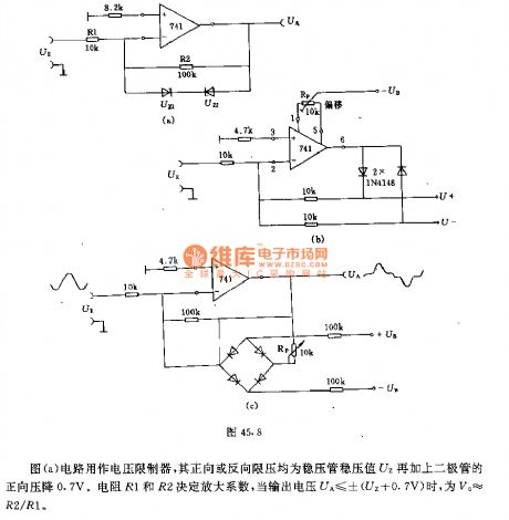
The circuit shown in Figure a is a voltage limiter, and its forward or reverse limit pressure is the zener regulator value UZ with adding 0.7V diode forward voltage drop. The resistors R1 and R2 determine the amplification coefficient, when the output voltage UA ≤ ± (UZ +0.7 V), V0 ≈ R2/R1.The circuit shown in Figure b can be used as a precision rectifier. It can output a positive or negative rectifier partial pressure according to the polarity requirements. It is often followed by the integrator in actual applications.Figure c shows the amplifier circuit with adjustable low input voltage and amplification factor. The size of dead zone can be adjusted by potentiometer.
Reprinted Url Of This Article:
http://www.seekic.com/circuit_diagram/Basic_Circuit/Limiter_and_rectifier_circuit_using_the_operational_amplifier.html
Print this Page | Comments | Reading(3)

Article Categories
power supply circuit
Amplifier Circuit
Basic Circuit
LED and Light Circuit
Sensor Circuit
Signal Processing
Electrical Equipment Circuit
Control Circuit
Remote Control Circuit
A/D-D/A Converter Circuit
Audio Circuit
Measuring and Test Circuit
Communication Circuit
Computer-Related Circuit
555 Circuit
Automotive Circuit
Repairing Circuit
Code: