Basic Circuit
LOW_VOLTAGE_BATTERY_SWITCHOVER_SYSTEM
Published:2009/7/13 22:00:00 Author:May | From:SeekIC
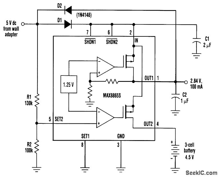
Portable systems often include the flexibility to operate either from an internal battery or from an ac-dc wall adapter. Many such systems include circuitry that switches automatically between an internal battery and an external source as the user connects and disconnects the wall adapter. The circuit shown implements this idea with a dual linear regulator, one side of which is preset for a regulated output of 2.84 V.(other versions of the IC offer 2.80-V and 3.15-V outputs). The other side of the regulator id configured to allow user-adjustable outputs, but, in this case, it monitors the wall-adapter voltage. When that voltage is removed by unplugging the adapter, the regulator's pass transistor routes battery current into the IC for support of the 2.84-V output (current flow in this transistor is counter to that of most applications). The input bypass capacitor (C1) provides enough holdup time for seamless transitions between the battery and adapter voltages. Resistors RI and R2 sense the wall-adapter voltage and determine the switchover threshold, 'VSW VSW = Vset【(R1+R2)/R2】 = 1.25V【(130kΩ+100kΩ)/100kΩ】 = 2.875vDiode Dl isolates the wall-adapter voltage so that the battery can't cause limit cycling by retriggering the switchover. D2 holds the IC's dual-mode input in the external feedback mode by maintaining a minimum voltage at the SET2 input. The wall-adapter voltage should be equal to or greater than the maximum battery voltage.
Reprinted Url Of This Article:
http://www.seekic.com/circuit_diagram/Basic_Circuit/LOW_VOLTAGE_BATTERY_SWITCHOVER_SYSTEM.html
Print this Page | Comments | Reading(3)

Article Categories
power supply circuit
Amplifier Circuit
Basic Circuit
LED and Light Circuit
Sensor Circuit
Signal Processing
Electrical Equipment Circuit
Control Circuit
Remote Control Circuit
A/D-D/A Converter Circuit
Audio Circuit
Measuring and Test Circuit
Communication Circuit
Computer-Related Circuit
555 Circuit
Automotive Circuit
Repairing Circuit
Code: