Basic Circuit
LOW_POWER_WIDE_SUPPLY_RANGE_CLOCK
Published:2009/7/12 20:34:00 Author:May | From:SeekIC

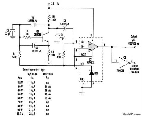
This 32-kHz, low-power clock oscillator offers numerous advantages over conventional oscillator circuits based on a CMOS inverter.Many times, 32-kHz oscillators are used to generate a system clock or an auxiliary sleep clock in low-power instruments and microcontrollers. The typical implementation uses a CMOS inverter (74HC04 or CD4049UB type). Inverter circuits present problems, though. Supply currents fluctuate widely over a 3- to 6-V supply range, and currents below 250 μA are difficult to attain. Operation can be unreliable for wide variations in supply voltage. A very low power crystal oscillator solves these problems. Drawing only 13μA from a 3-V supply, it consists of a single-transistor amplifier/oscillator (Q1) and a low-power comparator/reference device (IC1). Q1's base is biased at 1.25V via R5, R4, and the reference in IC1. VBE is about 0.7 V, placing the emitter at approximately 0.5 V. This constant voltage across R3 sets the transistor's quiescent current at 5μA, which fixes the collector voltage at about 1 V below VCC. The amplifier's nominal gain (R1/R2) is approximately 2 V/V The crystal and load capacitors (C1 attd C3) form a feedback path around Q1, whose 180°of phase shift causes the oscillation. C4 couple this singal to the comparator input;the input's quiescent voltage (1.25V) is set by the reference via R2.The comparator's input swing is thus centered around the reference voltage. Operating at 3V and 32 KHz,IC1 draws about 7μA.
Reprinted Url Of This Article:
http://www.seekic.com/circuit_diagram/Basic_Circuit/LOW_POWER_WIDE_SUPPLY_RANGE_CLOCK.html
Print this Page | Comments | Reading(3)

Article Categories
power supply circuit
Amplifier Circuit
Basic Circuit
LED and Light Circuit
Sensor Circuit
Signal Processing
Electrical Equipment Circuit
Control Circuit
Remote Control Circuit
A/D-D/A Converter Circuit
Audio Circuit
Measuring and Test Circuit
Communication Circuit
Computer-Related Circuit
555 Circuit
Automotive Circuit
Repairing Circuit
Code: