Basic Circuit
LOW_CURRENT_CONSUMPTION_LAMP_FLASHER
Published:2009/6/30 23:04:00 Author:May | From:SeekIC

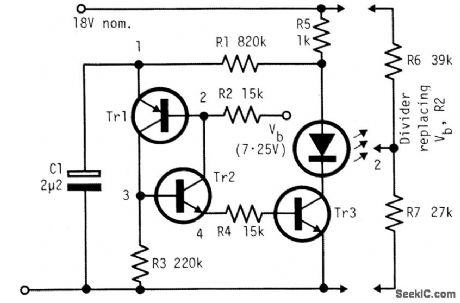
The circuit is economical in components, and will work with virtually any transistors and is reliably self-starting. The voltage Vb can be taken from a divider, as shown at the right. If taken from a fixed source, flashing becomes slower as battery voltage falls.The lowest drive current into the base of Tr3 is about (Vb-0.6 V)/(R2 + R4). Resistor R4 limits the initial current from C1 and, as shown, R2 and R4 can be roughly equal when a divider is used for Vb. Resistor R2 equals R6R7/(R6+ R7). With the voltages shown, and with R2 = R4, the on-time is about 1.1 C1R2 and the off-time about 0.28 C1R1. Using the component values shown the period is about 0.55 sec. with a duty cycle of about 7% and a mean battery current including the Vb divider, about 1.5 mA.
Reprinted Url Of This Article:
http://www.seekic.com/circuit_diagram/Basic_Circuit/LOW_CURRENT_CONSUMPTION_LAMP_FLASHER.html
Print this Page | Comments | Reading(3)

Article Categories
power supply circuit
Amplifier Circuit
Basic Circuit
LED and Light Circuit
Sensor Circuit
Signal Processing
Electrical Equipment Circuit
Control Circuit
Remote Control Circuit
A/D-D/A Converter Circuit
Audio Circuit
Measuring and Test Circuit
Communication Circuit
Computer-Related Circuit
555 Circuit
Automotive Circuit
Repairing Circuit
Code: