Basic Circuit
LOU_COST_CHIME_CIRCUIT
Published:2009/7/2 4:11:00 Author:May | From:SeekIC

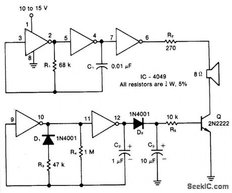
Resistor R1, capacitor C1, and two inverters form a square wave generator, which produces the basic tone. The generator is followed by an inverter that acts as both a buffer and a driver for the speaker. Resistor R2, which has a minimum value of 100 ohms, limits the current and controls the volume. Diode D1, ca-pacitor C2, resistors R3 and R4, and two inverters create the pulse generator that determines the turn-on and decay times of the chime. The decay circuit-formed by D2, C3, R5, and Q-reduces the amplitude of the chime tone exponentially as a function of time.
Reprinted Url Of This Article:
http://www.seekic.com/circuit_diagram/Basic_Circuit/LOU_COST_CHIME_CIRCUIT.html
Print this Page | Comments | Reading(3)

Article Categories
power supply circuit
Amplifier Circuit
Basic Circuit
LED and Light Circuit
Sensor Circuit
Signal Processing
Electrical Equipment Circuit
Control Circuit
Remote Control Circuit
A/D-D/A Converter Circuit
Audio Circuit
Measuring and Test Circuit
Communication Circuit
Computer-Related Circuit
555 Circuit
Automotive Circuit
Repairing Circuit
Code: