Basic Circuit
LOOP_ANTENNA_FOR_35_MHz
Published:2009/7/8 23:22:00 Author:May | From:SeekIC


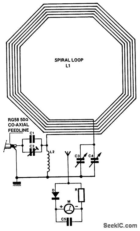
C1=3750 pF 500 V siver-mica capacitor.C2=100 pF preset capacitor(Jackson C803)C3=75 pF variable capacitor(Jackson C809),plus knob.C4=12.7 pF variable capacitor(Jackson C16),plus knob.C5=22 nF mica capacitor.M=250 μA f.s.d.40×40 mm moving coil meter(Maplin LB8O8).D=HF silicon diode.R=1 kΩ resistor(see text).L1=51/8 turns of PVC covered stranded 7/O.2 mm wlre,Outside diameter:1.2mm,1 kV/1.5 A rating(see text)L2=13 turns 16SWG tinned wlre,1 inch internal diameter.Feedline=48 inch RG58 coaxial cable,plus plug to suit transmitter.Box=ABS box type MB3,118×96×45 mm Maplin ref LH22.Terminal blocks=qty,412-way 2 amp terminal block Maplin ref,FE78.Spacers=qty.3 insulated spacer type M3,30 mm long,Mapin ref.FS4OT.Spokes=qty.48-foot lengths of 5/8×l/4inch molded hardwood(DIY store).Vertical support=23×O.8×0,Sinch wood(DIY store).Wood base=12×8×0.5 inch plywood or simiar.21/2 inch steel support bracket.
1. 4 lengths molded hardwood 3O x 5/8 x 1/4 Varnished. 2BA holes drilled in the centre. Glued and bolted together.2. 8 off 6-way 2-amp polythene terminal blocks used as insulated wire spacers.3. 51/8 turns of PVC stranded wire (for specs see component, list).4. See Fig. 3.5. Wood vertical support 23 x0.8 x0.8 , wood stained.6. 2 x 2BA bolt.7. Box front vertical support, 41/2 x 1/2 x 3/4 , wood stained.8. Wood base 12 x 8 x1/2 (for similar), wood stained.9. 21/2 steel support bracket behind wood vertical support.10. Drilled and secured with glue and c/s wood screws.Note: = inch=2.54cm.
Suitable for receiving or transmitting (10 W or less) on the 80-m band, this loop antenna might be helpful when an outside antenna is not possible.
Reprinted Url Of This Article:
http://www.seekic.com/circuit_diagram/Basic_Circuit/LOOP_ANTENNA_FOR_35_MHz.html
Print this Page | Comments | Reading(3)

Article Categories
power supply circuit
Amplifier Circuit
Basic Circuit
LED and Light Circuit
Sensor Circuit
Signal Processing
Electrical Equipment Circuit
Control Circuit
Remote Control Circuit
A/D-D/A Converter Circuit
Audio Circuit
Measuring and Test Circuit
Communication Circuit
Computer-Related Circuit
555 Circuit
Automotive Circuit
Repairing Circuit
Code: