Basic Circuit
LONG_DELAY_LINE_FOR_LOGIC_SIGNALS
Published:2009/7/7 3:55:00 Author:May | From:SeekIC


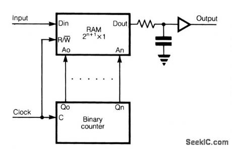
An extremely long delay of logic signal can be accomplished with this circuit. The logic signals to be delayed are applied to the,DIN of RAM. Address lines Ao,A1, . An are connected to outputs Qo, Q1, …… Qn of a binary counter. Clock input of counter and R/W input of RAM are joined together. However, it is sometimes necessary to put an inverter between those inputs, depending on the RAM and counter employed in line. In the first half of clock interval, content on outputs of counter is increased for 1 and content of chosen memory cell is read; in the second half of the clock interval, new content from DIN in the same memory cell is written. When full cycles of counting reaches the same memory cell, again we can read, in the first half of the clock interval of the following counting cycles, the chosen content. Delay time is:
Td=2 n+1·tcl
If clock frequency is not a multiple of input signal frequency, distortion of input signal is proportioned to the clock period. But if the clock frequency is a multiple of input signal frequency, there is no distortion. If we use RAM organized according to 2n+1 x 4 with separated data inputs and data outputs, we can have four parallel long delay lines. The resistor, capacitor, and buffer on DOUT of RAM are used to save output signal in writing time, when output of RAM becomes high impedance.
Reprinted Url Of This Article:
http://www.seekic.com/circuit_diagram/Basic_Circuit/LONG_DELAY_LINE_FOR_LOGIC_SIGNALS.html
Print this Page | Comments | Reading(3)

Article Categories
power supply circuit
Amplifier Circuit
Basic Circuit
LED and Light Circuit
Sensor Circuit
Signal Processing
Electrical Equipment Circuit
Control Circuit
Remote Control Circuit
A/D-D/A Converter Circuit
Audio Circuit
Measuring and Test Circuit
Communication Circuit
Computer-Related Circuit
555 Circuit
Automotive Circuit
Repairing Circuit
Code: