Basic Circuit
LIGHT_PEN
Published:2009/7/6 20:26:00 Author:May | From:SeekIC

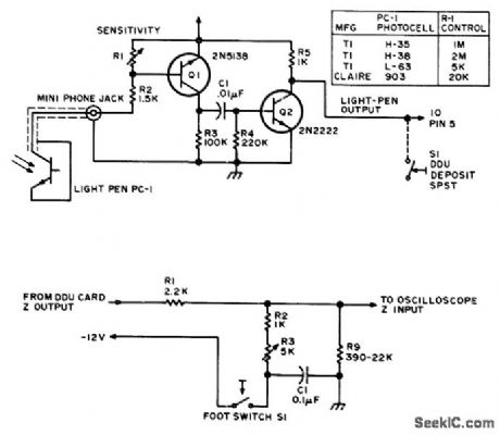
Photocell in tip of light pen senses when dot is written on screen at its location by becoming conductive and biasing al so it feeds short pulse through 01 to base of 02. If pulse is greater than 0.6V, Q2 is driven into saturation and output of pen drops to 0.3 V. Output line goes to pin 5 of digital display unit (DDU), which writes 1 or 0 (dot or no dot! on screen at instant that electron beam of CRT terminal reaches position of pen. Sensitivity control can be adjusted so illuminated dot just ahead of pen can be used to create new dot in adjacent dark space. If screen is dark all around pen, footswitch-con-trolled auxiliary circuit can be used to override Z-axis control and flood screen with light momentarily by feeding logic 1 to2 input. This mode can be used for creating or correcting graphics.-S. S. Loomis, Let There Be Light Pens, BYTE, Jan, 1976, p 26-30.
Reprinted Url Of This Article:
http://www.seekic.com/circuit_diagram/Basic_Circuit/LIGHT_PEN.html
Print this Page | Comments | Reading(3)

Article Categories
power supply circuit
Amplifier Circuit
Basic Circuit
LED and Light Circuit
Sensor Circuit
Signal Processing
Electrical Equipment Circuit
Control Circuit
Remote Control Circuit
A/D-D/A Converter Circuit
Audio Circuit
Measuring and Test Circuit
Communication Circuit
Computer-Related Circuit
555 Circuit
Automotive Circuit
Repairing Circuit
Code: