Basic Circuit
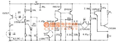
Infrared remote monitoring circuit schematics
Published:2014/4/16 20:47:00 Author:lynne | Keyword: Infrared remote monitoring circuit schematics | From:SeekIC

The circuit shown in Figure can be transmitted over a long distance signal detected target. PC1 infrared diode and phototransistor pair, when a target object or irradiating light barrier diode phototransistor, the phototransistor is turned on in the turned off, and through amplification and second infrared diode and phototransistor and power amplifier for transmission to the load (alarm or lights), the second of the infrared diode and phototransistor pair from the fail-safe action. Infrared remote monitoring circuit diagram shown in Figure:
Reprinted Url Of This Article:
http://www.seekic.com/circuit_diagram/Basic_Circuit/Infrared_remote_monitoring_circuit_schematics.html
Print this Page | Comments | Reading(3)

Article Categories
power supply circuit
Amplifier Circuit
Basic Circuit
LED and Light Circuit
Sensor Circuit
Signal Processing
Electrical Equipment Circuit
Control Circuit
Remote Control Circuit
A/D-D/A Converter Circuit
Audio Circuit
Measuring and Test Circuit
Communication Circuit
Computer-Related Circuit
555 Circuit
Automotive Circuit
Repairing Circuit
Code: