Basic Circuit
ISOLATION_AND_ZERO_VOLTAGE_SWITCHING_LOGIC
Published:2009/7/5 22:33:00 Author:May | From:SeekIC
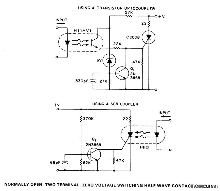
These two simple circuits provide zero voltage switching. They can be used with full wave bridges or in antiparallel to provide full wave control and are normally used to trigger power thyristors. If an input signal is present during the time the ac voltage is between 0 to 7 V, the SCR will turn on. But, if the ac voltage has risen above this range and the input signal is then applied, the transistor, Q1, will be biased to the on state and will hold the SCR and, consequently, the relay off until the next zero crossing.
Reprinted Url Of This Article:
http://www.seekic.com/circuit_diagram/Basic_Circuit/ISOLATION_AND_ZERO_VOLTAGE_SWITCHING_LOGIC.html
Print this Page | Comments | Reading(3)

Article Categories
power supply circuit
Amplifier Circuit
Basic Circuit
LED and Light Circuit
Sensor Circuit
Signal Processing
Electrical Equipment Circuit
Control Circuit
Remote Control Circuit
A/D-D/A Converter Circuit
Audio Circuit
Measuring and Test Circuit
Communication Circuit
Computer-Related Circuit
555 Circuit
Automotive Circuit
Repairing Circuit
Code: