Basic Circuit
INVERTED_MONO
Published:2009/7/1 20:03:00 Author:May | From:SeekIC

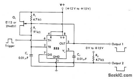
Connection shown for 555 timer accepts positive trigger pulses and delivers negative output pulses. Duty cycies above 99% are possible without jitter. Heavy loads can be driven from pin 7 without loss of accuracy, but excessive loading of pin 3 can affect timing accuracy. Width of output pulse is 1 ms for values of R1 and C1 shown. Trigger must be held, below two-thirds of supply voltage for standby I and raised above two-thirds of supply momentarily (not longer than pulse width) for triggering.-W. G. Jung, IC Timer Cookbook, Howard W. Sams, Indianapolis, IN, 1977, p 89.
Reprinted Url Of This Article:
http://www.seekic.com/circuit_diagram/Basic_Circuit/INVERTED_MONO.html
Print this Page | Comments | Reading(3)

Article Categories
power supply circuit
Amplifier Circuit
Basic Circuit
LED and Light Circuit
Sensor Circuit
Signal Processing
Electrical Equipment Circuit
Control Circuit
Remote Control Circuit
A/D-D/A Converter Circuit
Audio Circuit
Measuring and Test Circuit
Communication Circuit
Computer-Related Circuit
555 Circuit
Automotive Circuit
Repairing Circuit
Code: