Basic Circuit
INFRARED_CODE_PRACTICE_RECEIVER
Published:2009/7/12 20:47:00 Author:May | From:SeekIC

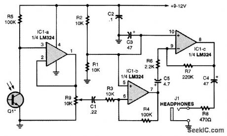
An IR phototransistor, Q1, is directly-coupled to the input of op amp IC1-a. The output of IC1-a is fed through the gain-control potentiometer R9 to the input of op amp IC1-b, which has a voltage gain of 10. Section IC1-b's output drives IC1-c, which has a voltage gain of 100. The output of IC1-c supplies audio to the heddphones via J1. The IR phototransistor can be mounted in reflectors to increase the CPO's operating range.
Reprinted Url Of This Article:
http://www.seekic.com/circuit_diagram/Basic_Circuit/INFRARED_CODE_PRACTICE_RECEIVER.html
Print this Page | Comments | Reading(3)

Article Categories
power supply circuit
Amplifier Circuit
Basic Circuit
LED and Light Circuit
Sensor Circuit
Signal Processing
Electrical Equipment Circuit
Control Circuit
Remote Control Circuit
A/D-D/A Converter Circuit
Audio Circuit
Measuring and Test Circuit
Communication Circuit
Computer-Related Circuit
555 Circuit
Automotive Circuit
Repairing Circuit
Code: