Basic Circuit
IMPROVED_NON_INVERTING_INTEGRATOR
Published:2009/7/1 1:06:00 Author:May | From:SeekIC

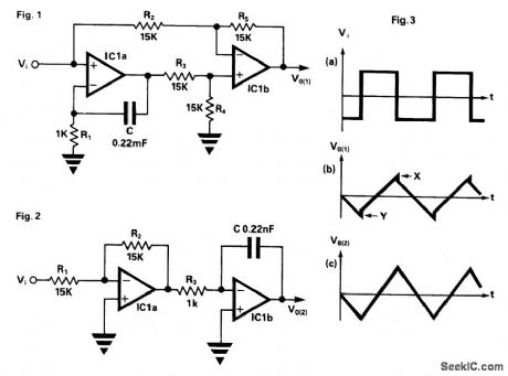
In the circuit in Fig. 1, IC1a produces the integral term required but also has the side effect of producing a proportional term not required, so this term is subtracted by IC1b leaving a pure integral. If the ratio R2/R5 does not exactly match the ratio of R3/R4, the subtraction will not be complete and a small amount of the proportional term will reach the output. The result of this with a squarewave input is shown in Fig. 3a as small steps in the output waveform at points X and Y.This effect can be completely removed by using the simplified circuit shown in Fig.2. Here the signal is pre-inverted by IC1a, then fed to a standard inverting integrator IC1b. The result is a non-inverting integrator with the advantage that the unwanted proportional term is never produced, so it does not need to be subtracted.
Reprinted Url Of This Article:
http://www.seekic.com/circuit_diagram/Basic_Circuit/IMPROVED_NON_INVERTING_INTEGRATOR.html
Print this Page | Comments | Reading(3)

Article Categories
power supply circuit
Amplifier Circuit
Basic Circuit
LED and Light Circuit
Sensor Circuit
Signal Processing
Electrical Equipment Circuit
Control Circuit
Remote Control Circuit
A/D-D/A Converter Circuit
Audio Circuit
Measuring and Test Circuit
Communication Circuit
Computer-Related Circuit
555 Circuit
Automotive Circuit
Repairing Circuit
Code: