Basic Circuit
High Q value trapped wave filter circuit
Published:2011/6/23 22:19:00 Author:TaoXi | Keyword: High Q value, trapped wave, filter circuit | From:SeekIC
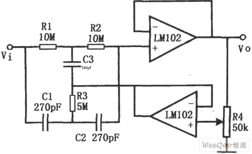
The high Q value trapped wave filter circuit is as shown in the figure. Because the double-T network filter can have the better attenuation characteristics only when it is far away from the resonance frequency f0, so the Q value of the filter is not high. If the output signal of the filter is output by the voltage output device (the gain is 1), and it is feedback to the double-T network to form the bootstrap, so when the input signal attenuates for 0.3, the Q value is more than 50. The voltage follower is composed of the op-amp, the potentiometer R4 can continuously change the Q value of the circuit (from 0.3 to 50), the trapped wave frequency f0=1/2πR1C1.
Reprinted Url Of This Article:
http://www.seekic.com/circuit_diagram/Basic_Circuit/High_Q_value_trapped_wave_filter_circuit.html
Print this Page | Comments | Reading(3)

Article Categories
power supply circuit
Amplifier Circuit
Basic Circuit
LED and Light Circuit
Sensor Circuit
Signal Processing
Electrical Equipment Circuit
Control Circuit
Remote Control Circuit
A/D-D/A Converter Circuit
Audio Circuit
Measuring and Test Circuit
Communication Circuit
Computer-Related Circuit
555 Circuit
Automotive Circuit
Repairing Circuit
Code: